
Lycoming
IO-580-B1A
Six angle-valve cylinders, a separate low induction housing, six long intake runners, forward injection and a top fuel manifold.
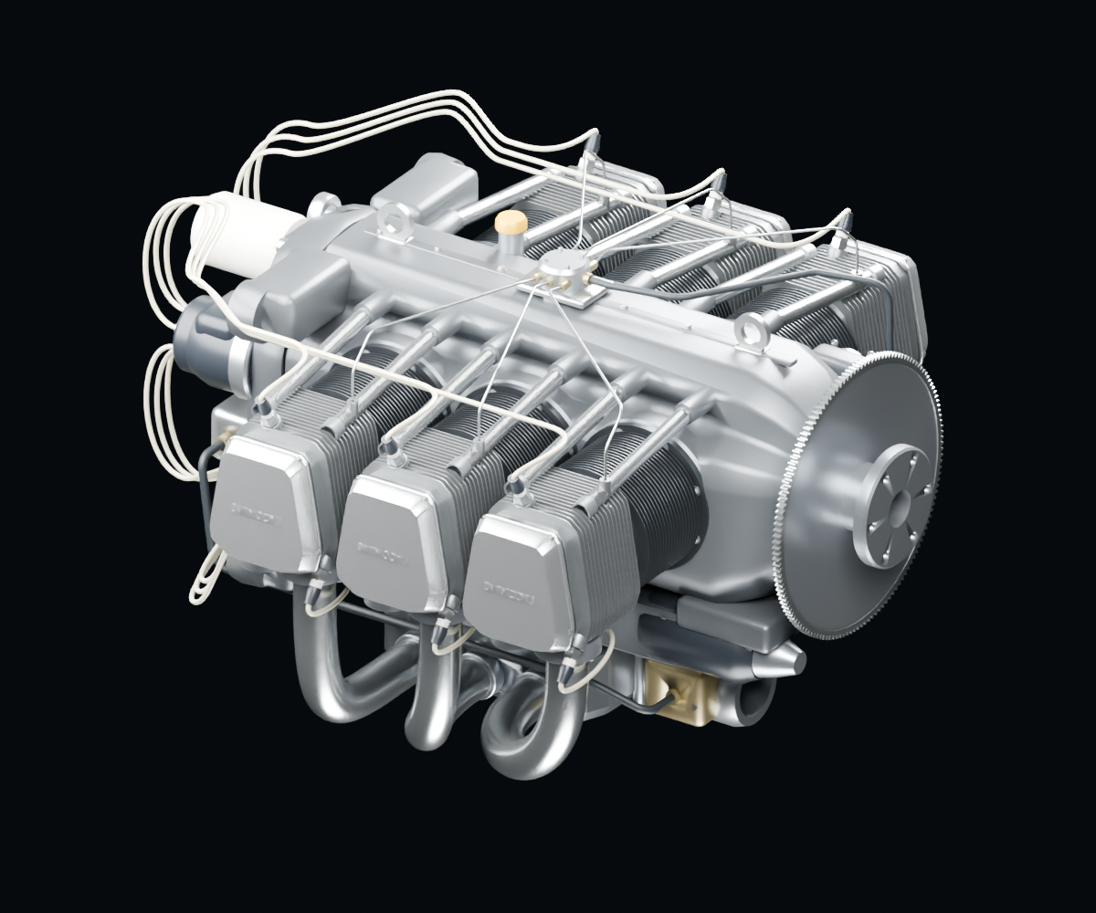
A saved render of this model. Load 3D to rotate and inspect it.
No citable kinematics for this engine yet
Drag to rotate; scroll or pinch to zoom. With the model focused, use arrow keys to rotate and + or − to zoom.
Explore an assembly
Select an assembly or a component to inspect its model evidence.
Model accuracy & scope
Reviewed exterior models with fitted geometry. Installed part numbers and component-level manual matching remain unverified unless explicitly identified.
- Reviewed first exterior; dimensions, routes and materials include fitted approximations. Not exact installed OEM geometry.
- Parts groups are a browsing aid, not an OEM exploded assembly or an installed parts catalogue.
- Internal mechanisms, functional flow and maintenance fit are not established.
- Oil returns occupy part of the bare exhaust approach; installed pipe clearance is not established.
- Raised ignition arches, bright castings and fine hardware remain refinement work.
Use the applicable manufacturer manual and parts catalogue for maintenance and exact installation details.
Manufacturer references
These references inform the model as a whole. A component is linked to a specific page or figure only when that match has been verified.
Lycoming IO-580-B1A Operator and Installation Manual 60297-28
Document host: www.lycoming.com
April 2003
Reference pages: I-2-1, Figs 2-1–2-3
Model architecture and illustrated envelope; not a manufacturing station drawing.
Lycoming IO-580-B1A Parts Catalog PC-701-1
Document host: www.lycoming.com
March 2003 cover; roller-tappet reissue date unresolved
Reference pages: Figs 14, 16, 21–23
Angle-valve heads, separate induction and fuel-system roles; installed PNs unresolved.