
Lycoming
IO-720-A1B
Eight opposed air-cooled cylinders with A1B front-inlet induction, fuel injection and paired rear magnetos.
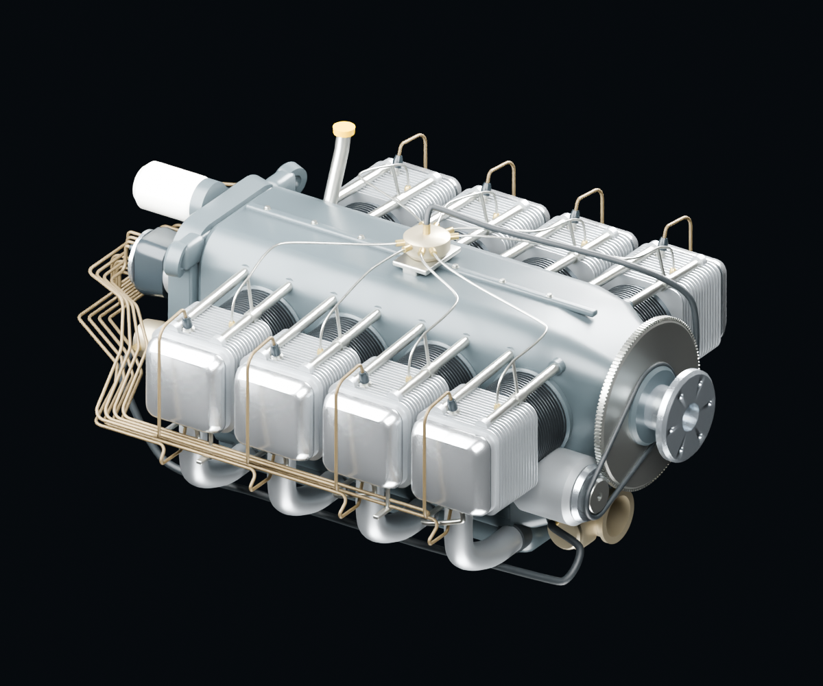
A saved render of this model. Load 3D to rotate and inspect it.
No citable kinematics for this engine yet
Drag to rotate; scroll or pinch to zoom. With the model focused, use arrow keys to rotate and + or − to zoom.
Explore an assembly
Select an assembly or a component to inspect its model evidence.
Model accuracy & scope
Reviewed exterior models with fitted geometry. Installed part numbers and component-level manual matching remain unverified unless explicitly identified.
- Reviewed first exterior; dimensions, routes and materials include fitted approximations. Not exact installed OEM geometry.
- Parts groups are a browsing aid, not an OEM exploded assembly or an installed parts catalogue.
- Internal mechanisms, functional flow and maintenance fit are not established.
- Eight harness/support contacts and a small manifold-end fuel-hose fold remain real deferred defects.
- Hollow drain collars receive capped tubes; internal oil drilling is absent.
- Exhaust openings are blind recesses; regular wiring and casting finish remain simplified.
Use the applicable manufacturer manual and parts catalogue for maintenance and exact installation details.
Manufacturer references
These references inform the model as a whole. A component is linked to a specific page or figure only when that match has been verified.
Lycoming IO-720 Parts Catalog PC-119
Document host: www.lycoming.com
November 1977 cover; page-level revisions retained
Reference pages: PDF 99–100, Fig 45, PDF 122, Fig 56
A1A/A1B front-inlet configuration and fuel-line support roles. Rear-inlet family photo is not A1B-specific.
Lycoming IO-720 Operator Manual 60297-19
Document host: www.lycoming.com
Fourth edition, October 2006
Reference pages: PDF 66, Fig 7-3
Front-inlet installation appearance; dimensions and installed accessory identity remain qualified.